


Constructing a 3D Printer [Prusa I3]
SECTION 4 - Extruder - Page 3
Section 1 - Wooden frame : part 1 - part 2 - part 3Section 2 - Y Axis : part 1 - part 2 - part 3
Section 3 - X-Z axis : part 1 - part 2
Section 4 - Extruder : part 1 - part 2 - [[ part 3 ]]
Section 5 - Electronics : part 1 - part 2 - part 3
Section 6 - Coarse Calibration & Software : part 1 - part 2 - part 3
Section 7 - Fine Calibration & Software : part 1 - part 2 - part 3
Section 8 - Extras : part 1 - part 2 - part 3
Section 9 - Maintenance & Modding : part 1 - part 2
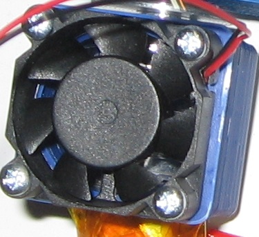
For the E3D v5 use the four screws (or only two diagonally) to secure the fan to the printed fan-mount, the fan must be mounted with the sticker facing the heatsink so that the fan blows over the heatsink.
Similarly for the E3D V6 :
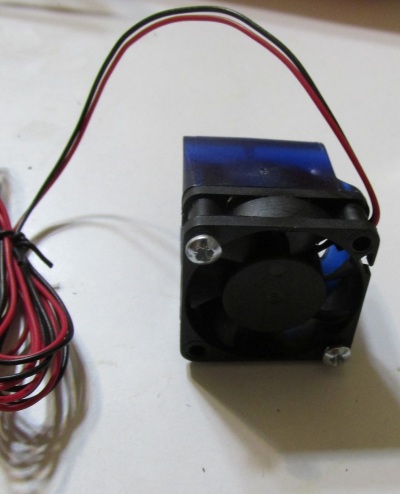
Clip the fan duct to the heatsink barrel.
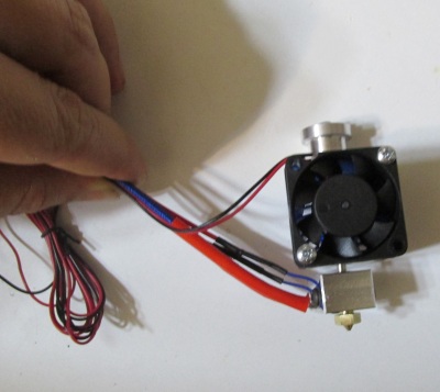
Do some cable managment for the E3D v6 using the zip tie :
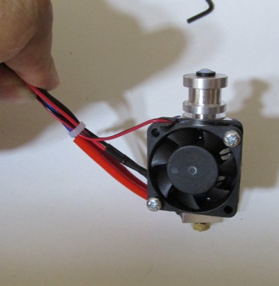
The final result of the E3D v6 can be seen below :
For the E3D v5 you should drill two M3 holes on the printed fan-mount like the photo below :
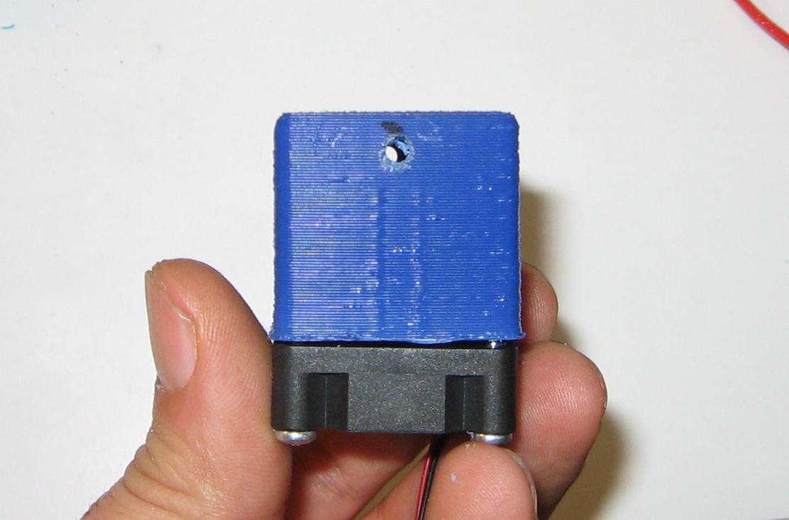
Now slide the barrel into the printed fan-mount
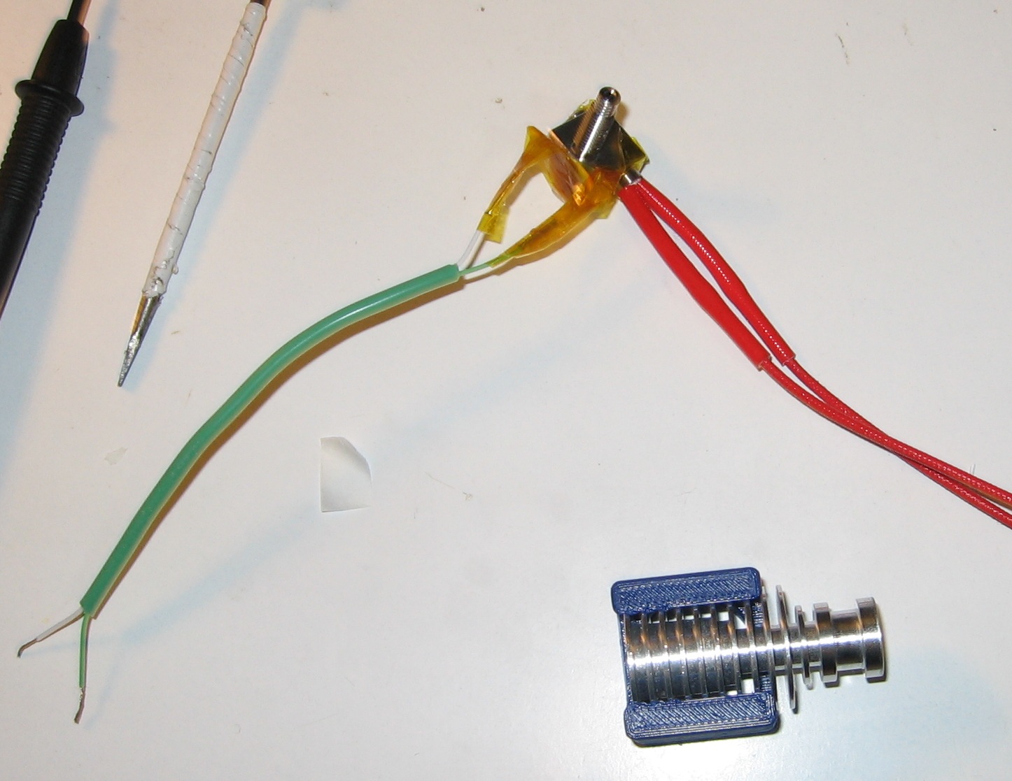
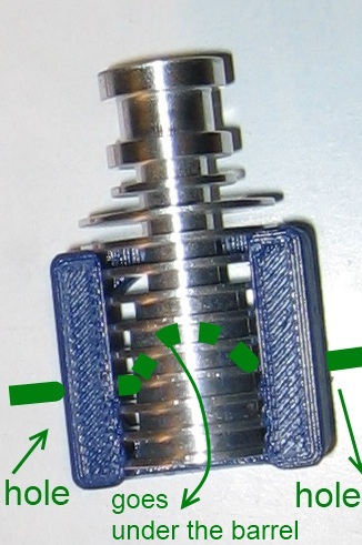
Pick a small shielded wire like these used to shield the bags and use it to block the barrel with the printed fan-mount.
By doing this you will prevent the fan-mount to rotate around the barrel.
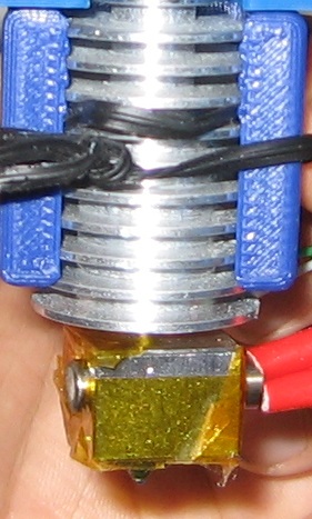
Now screw the heatsink onto the long end of the heat-break, firmly finger tight is fine.
Attention : using a spanner and over-torquing will snap the thermal break at the constriction.
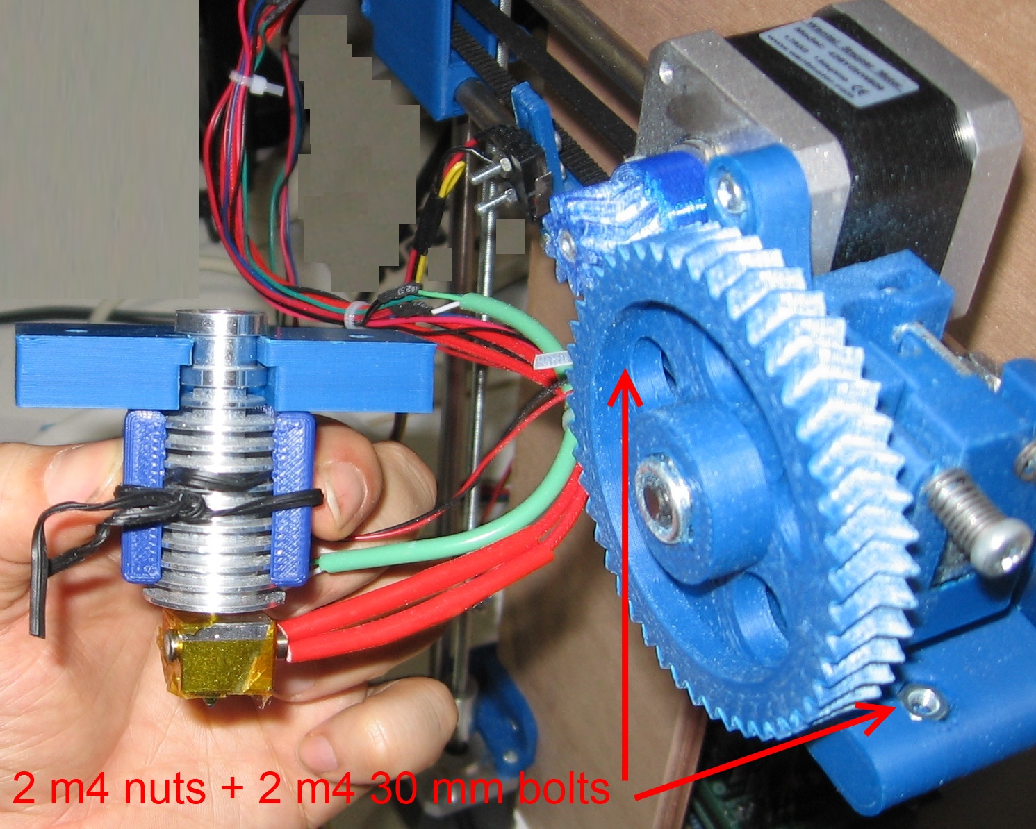
Now mount the hot end to the Greg's wade using the Groove mount part and two M4 30 mm bolts and two M4 nuts.
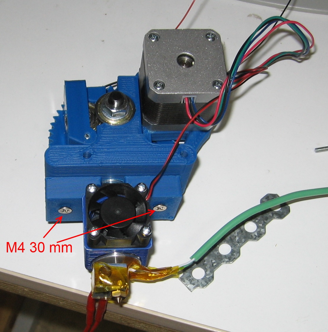
Do a cable managment like the picture below using zip ties :
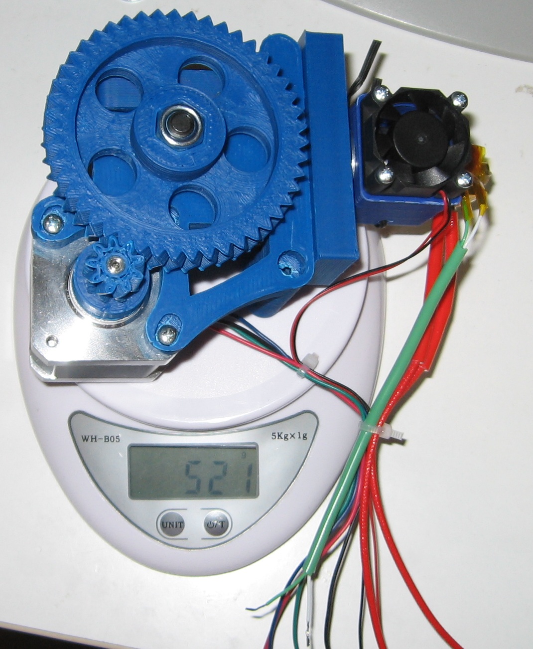
Notice that the hole extruder weights 521 gr.
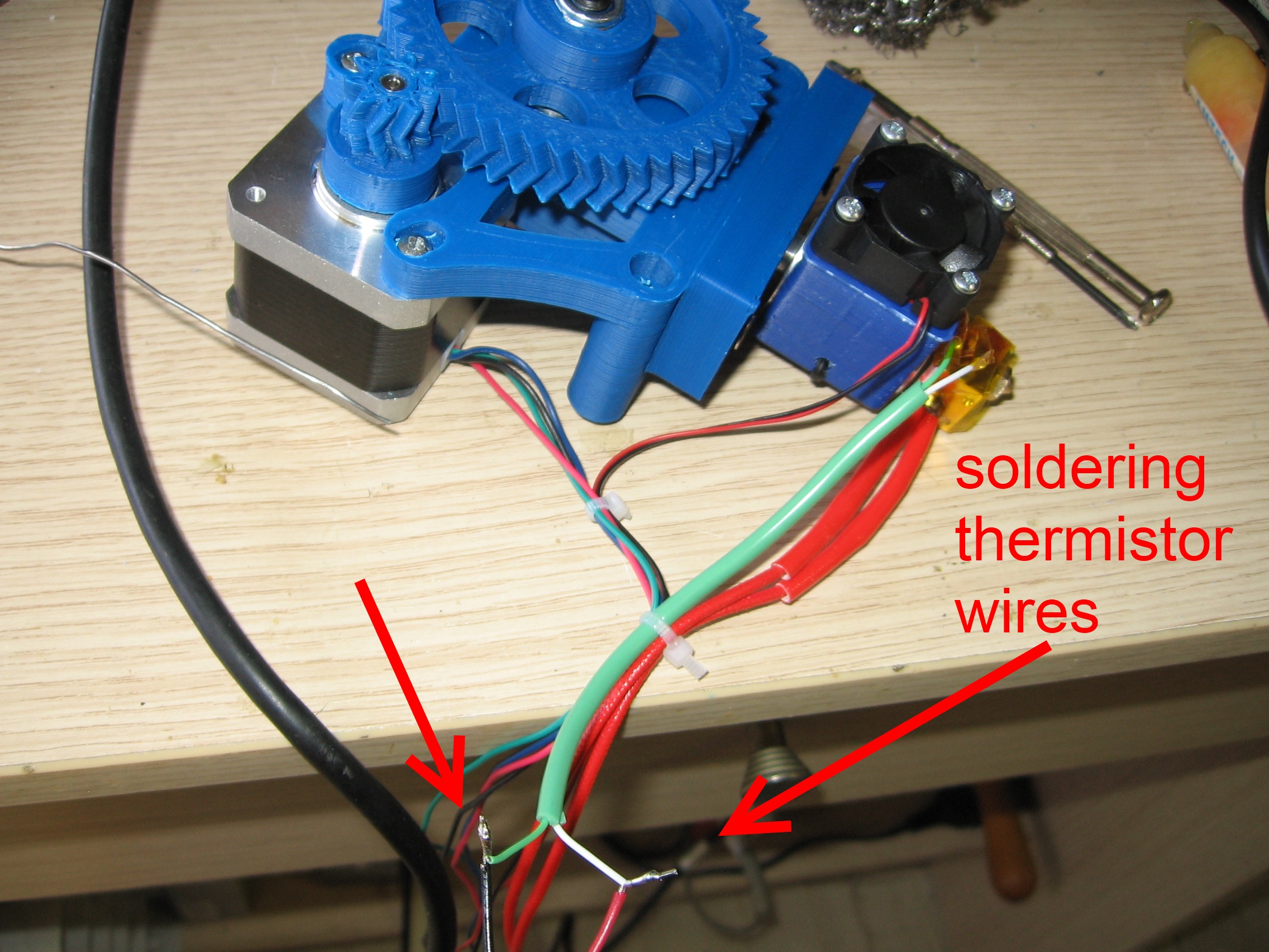
Solder and isolate with electrical tape the two wires of the thermistor.
Place two M3 nuts on the back of the X carriage.
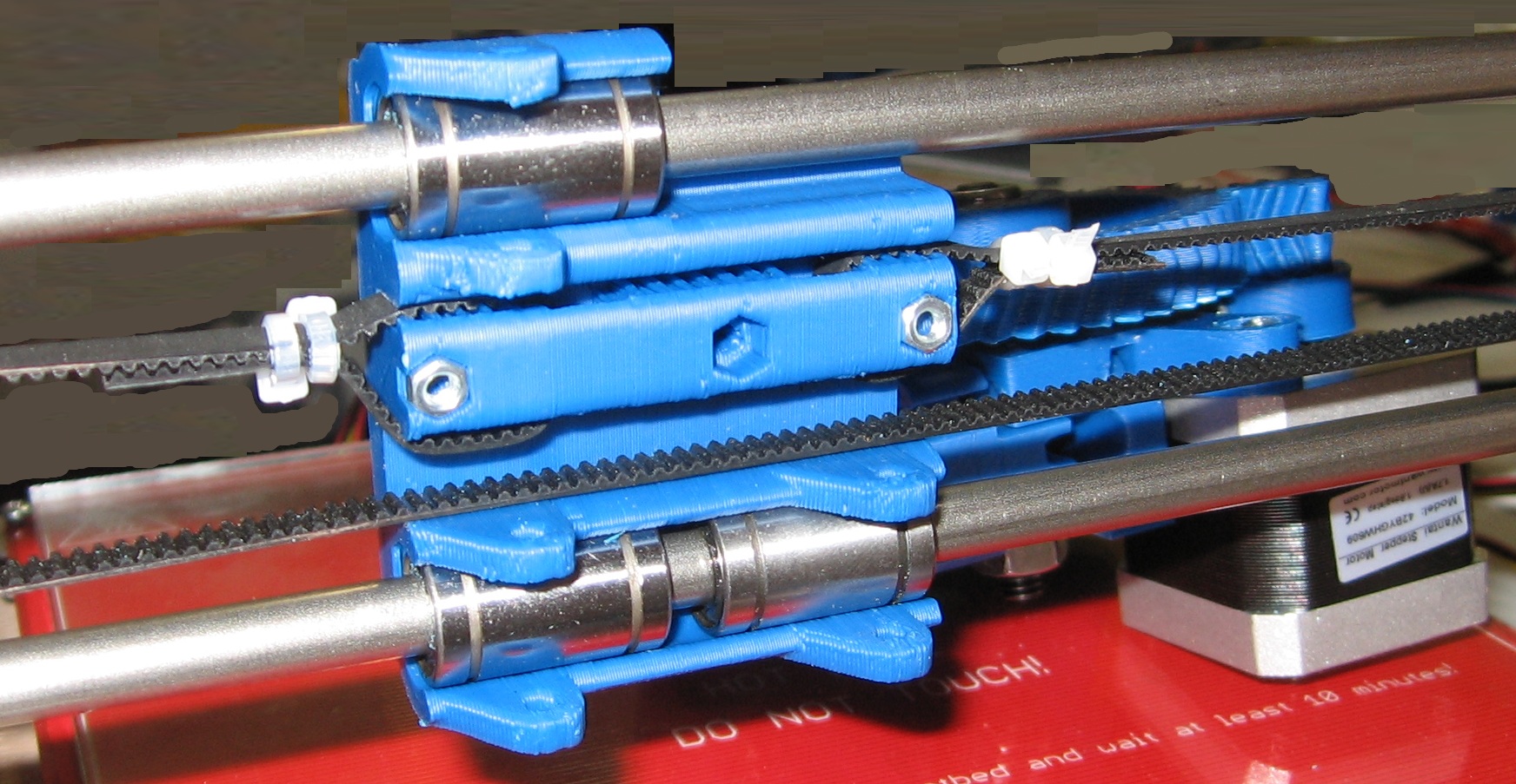
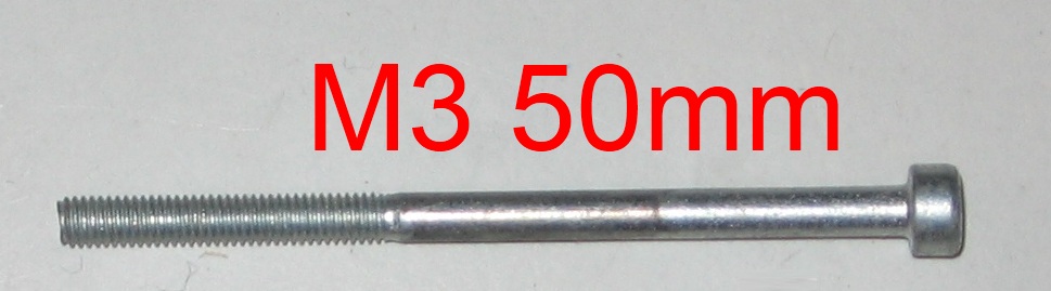
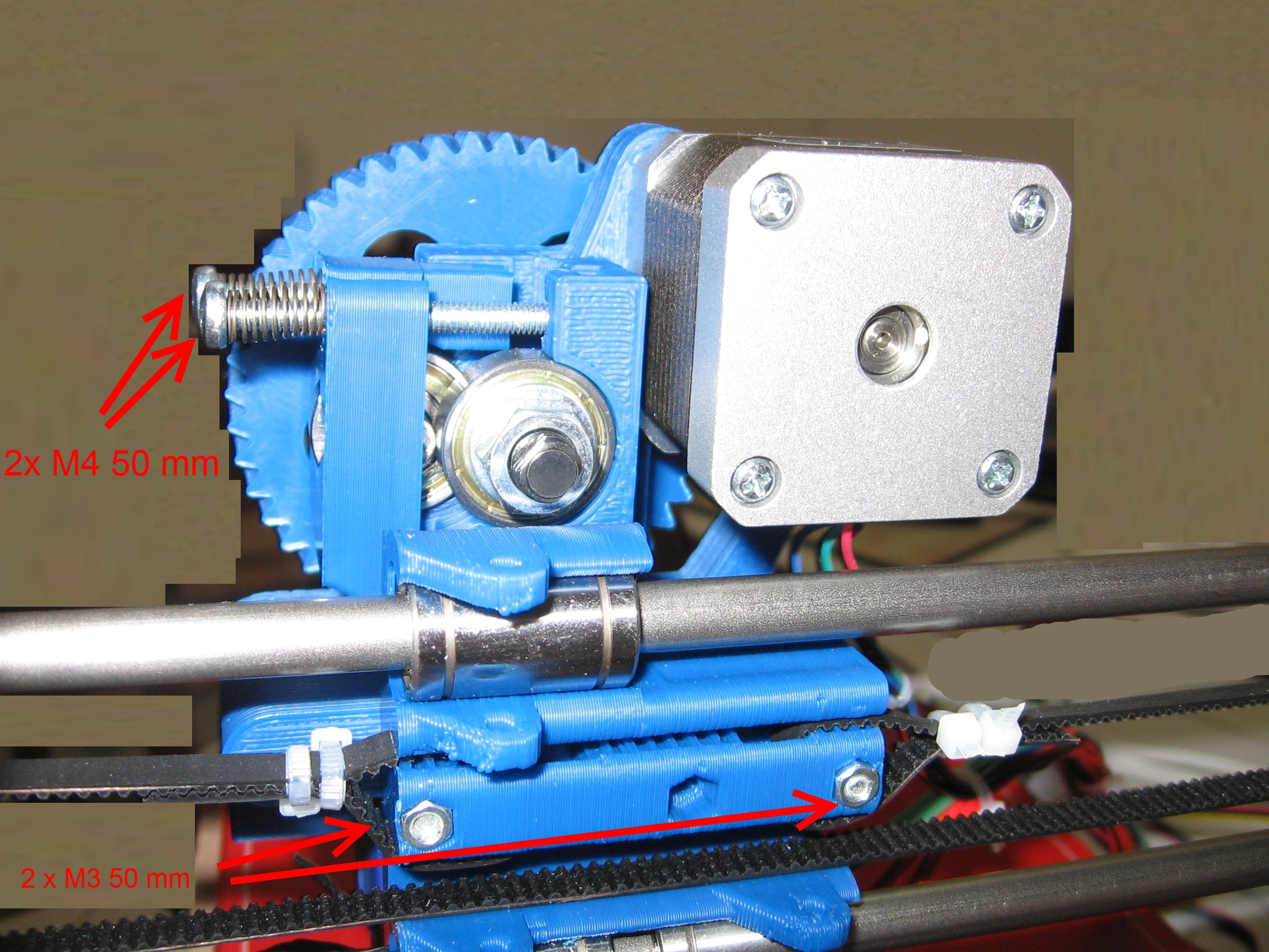
Now fix the extruder into the carriage using with two M3 50 mm hex bolts
Place two M4 nuts into the Greg's wage body.
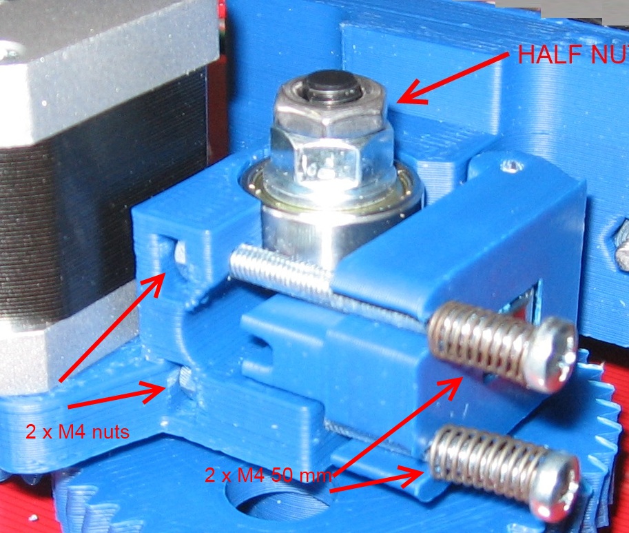
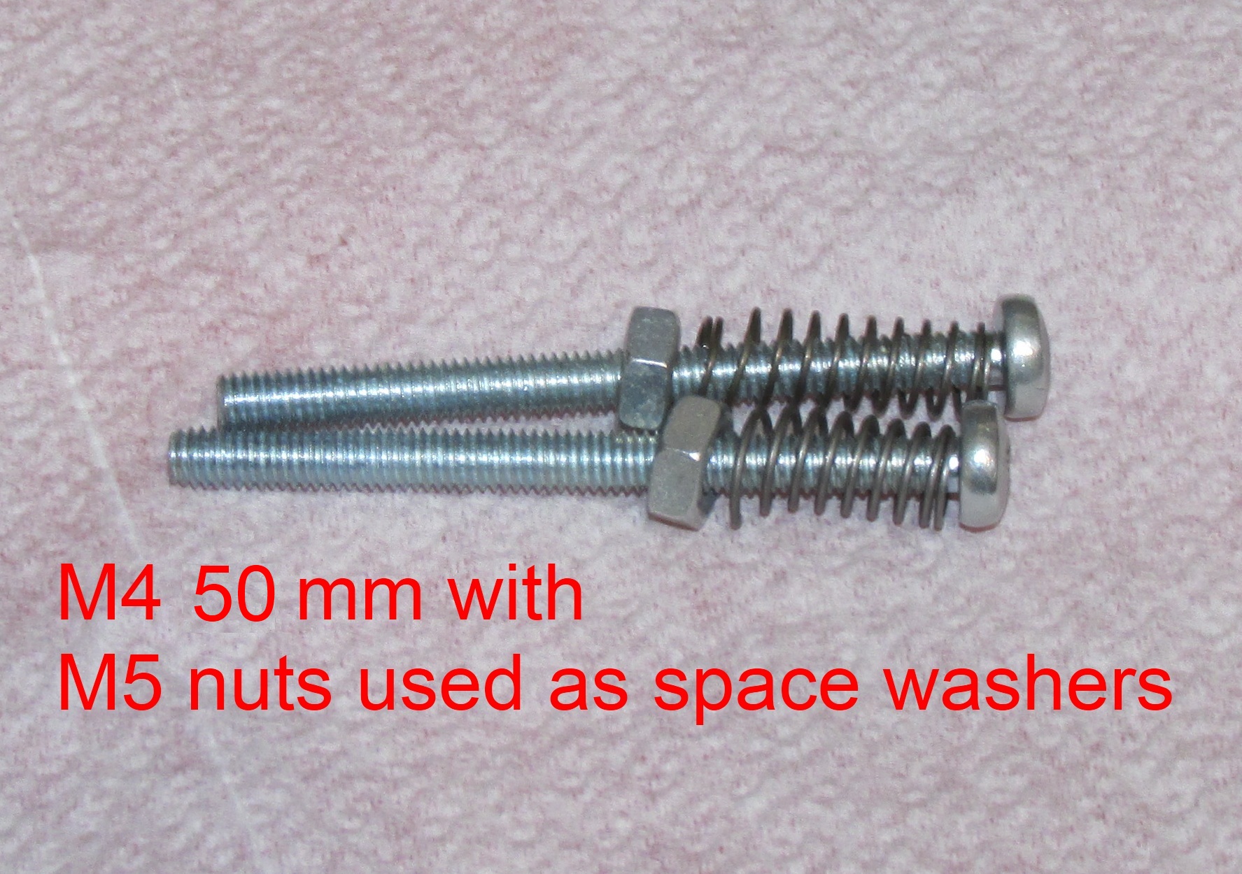
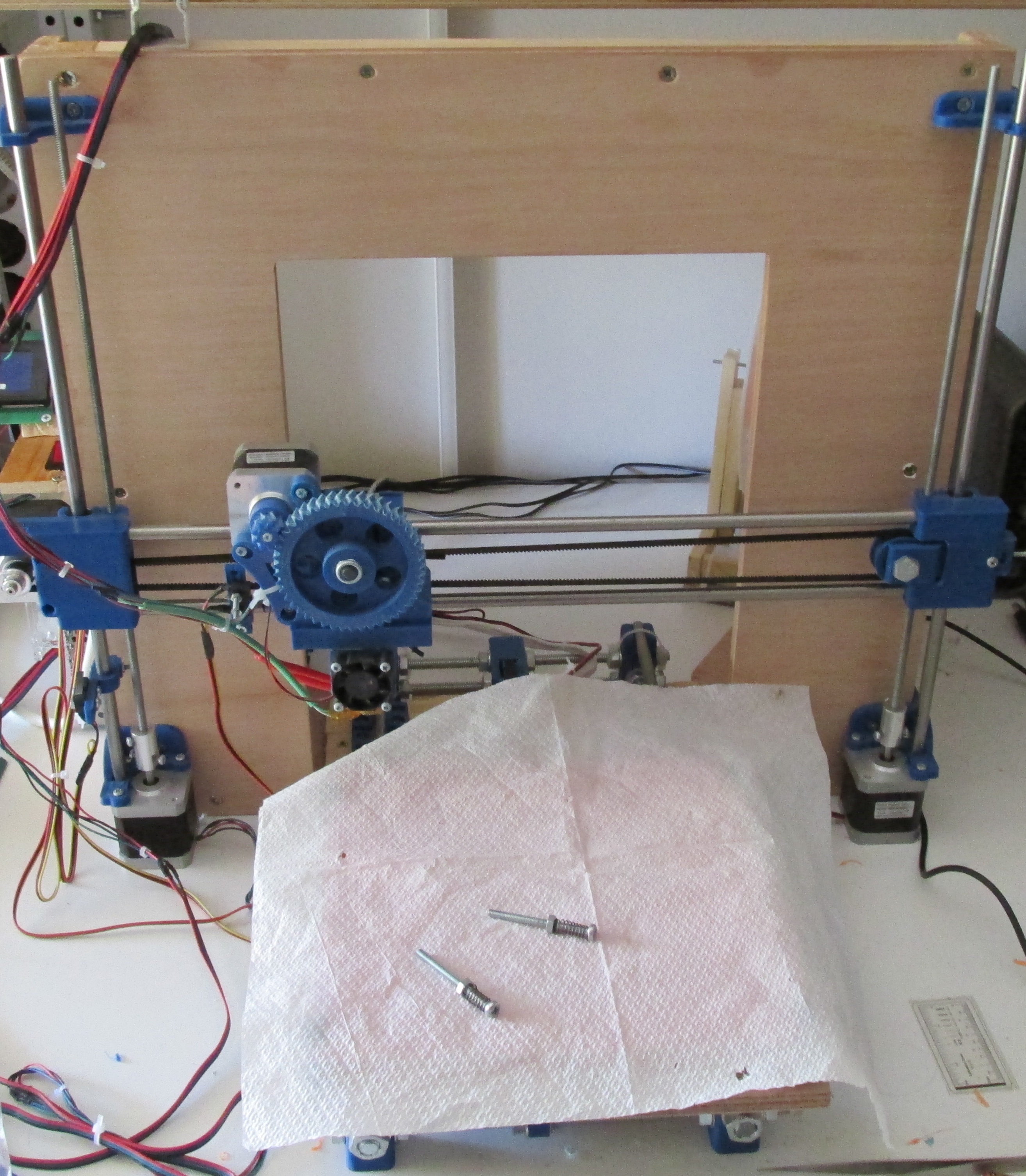
Now assemble two M4 50 mm screws like this :
Screw the two M4 screws in order to keep in place the extruder idler.
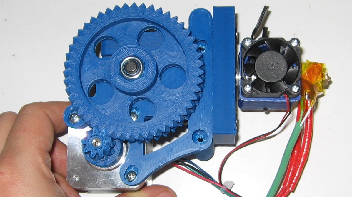
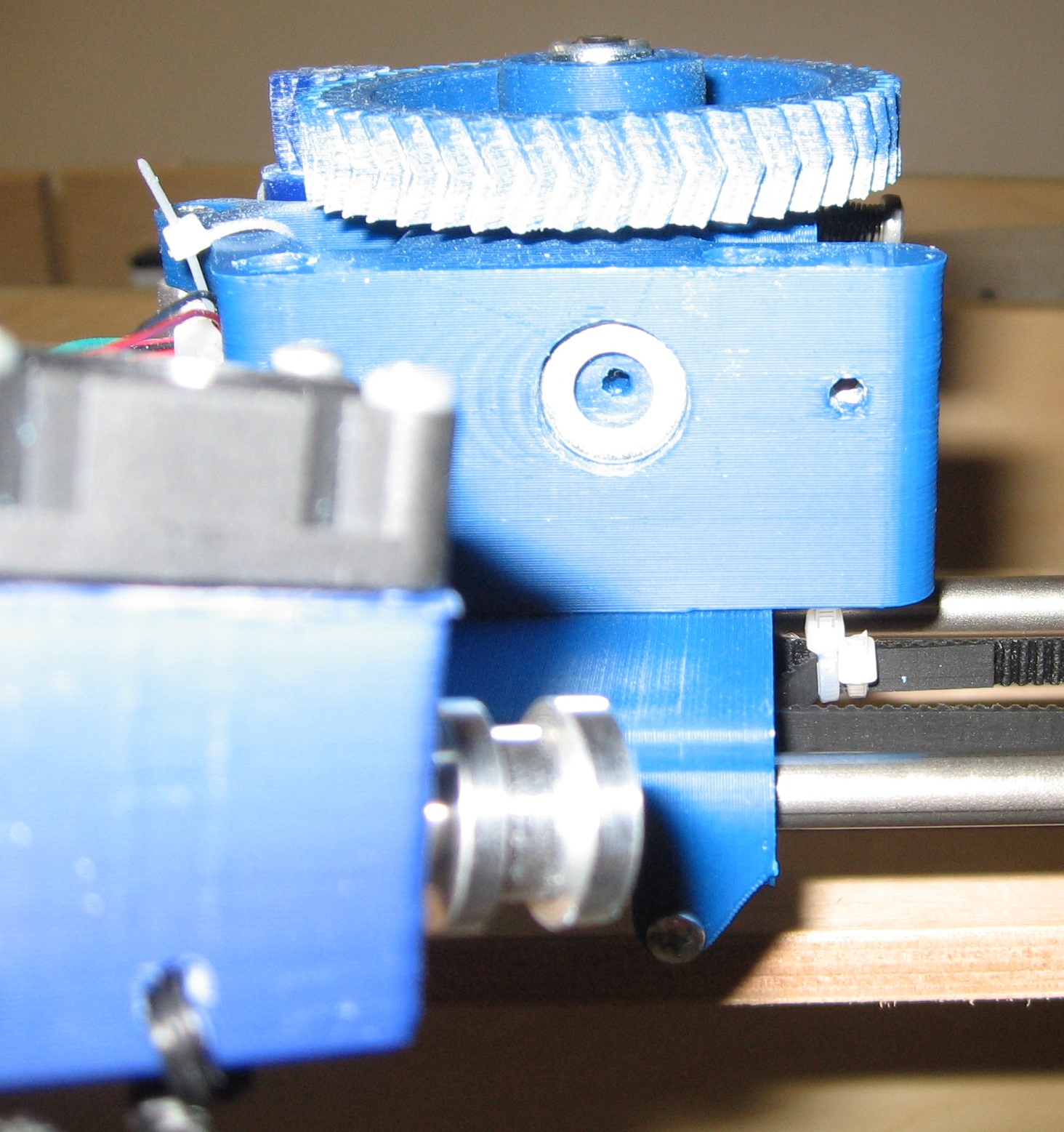
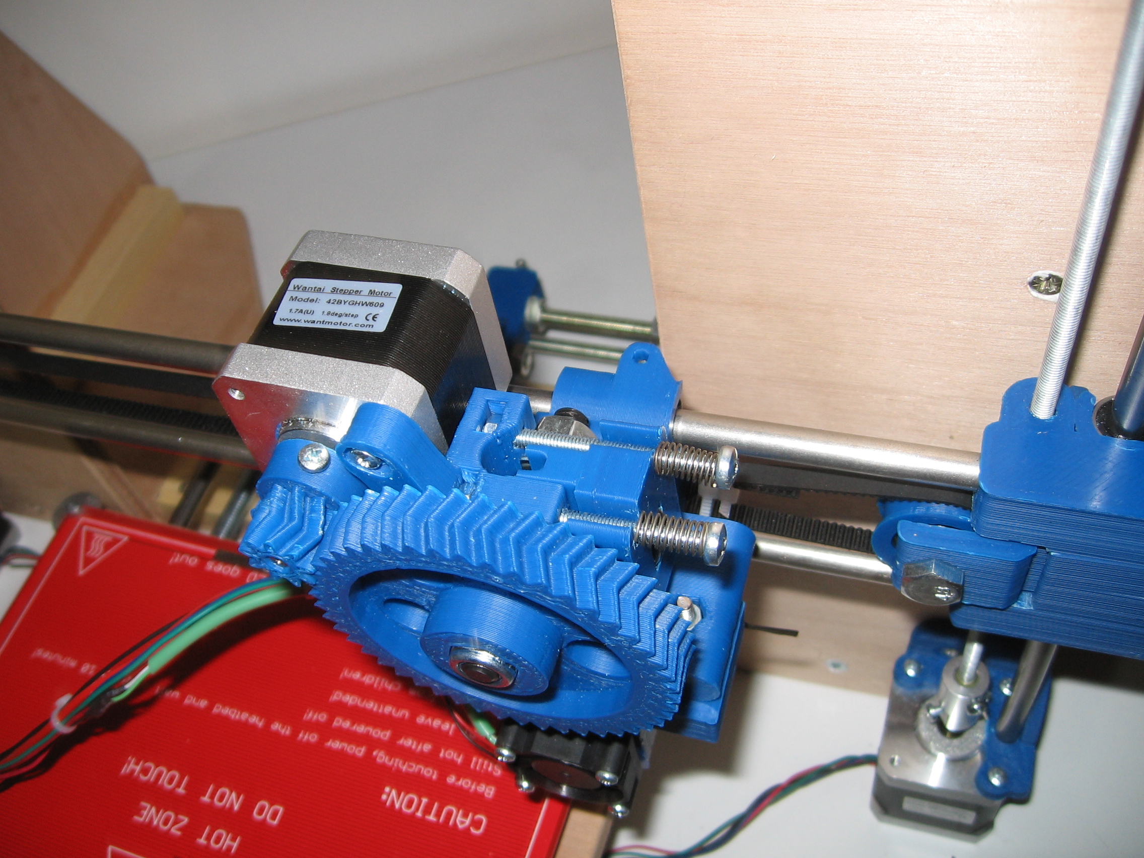
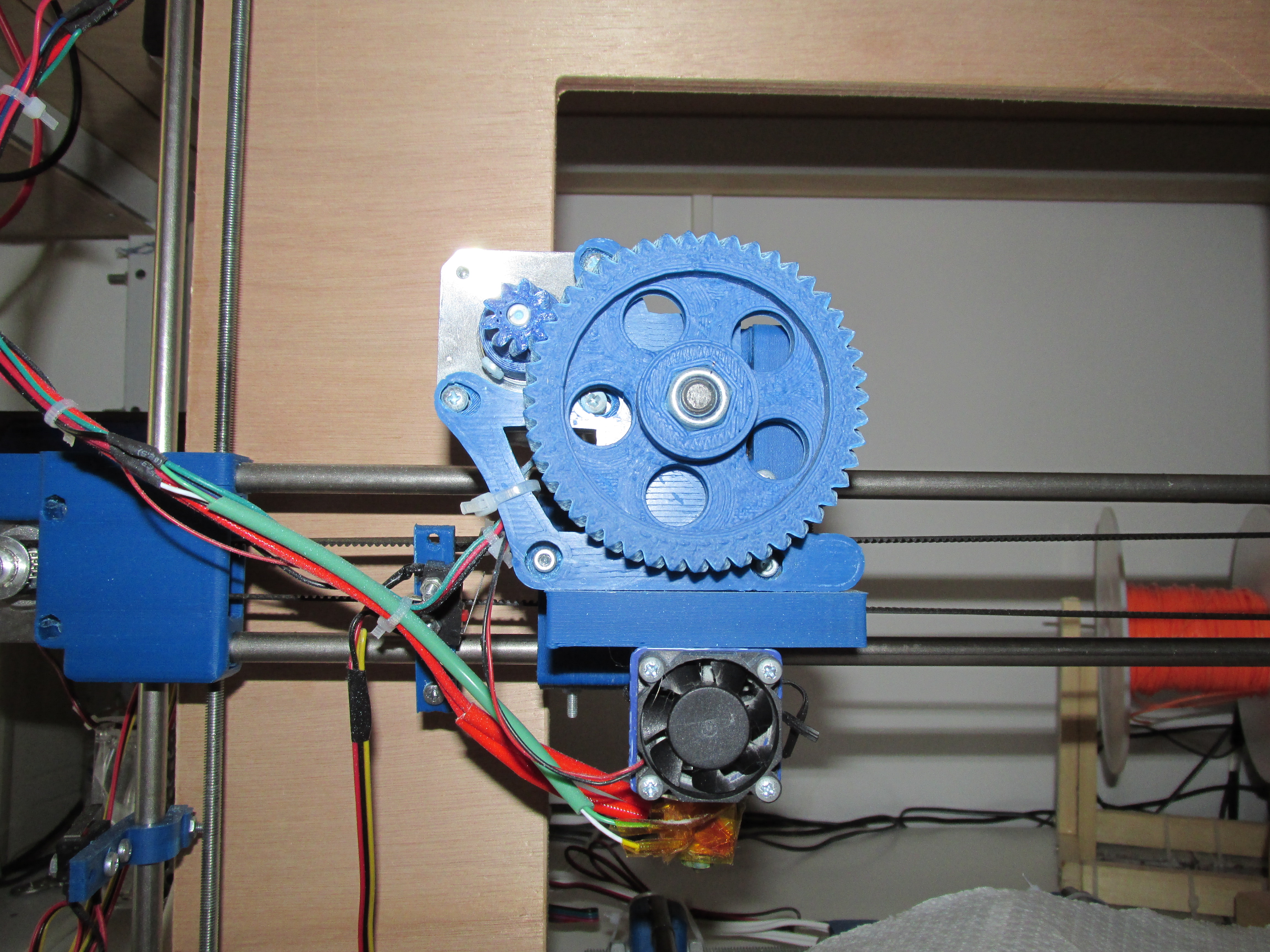
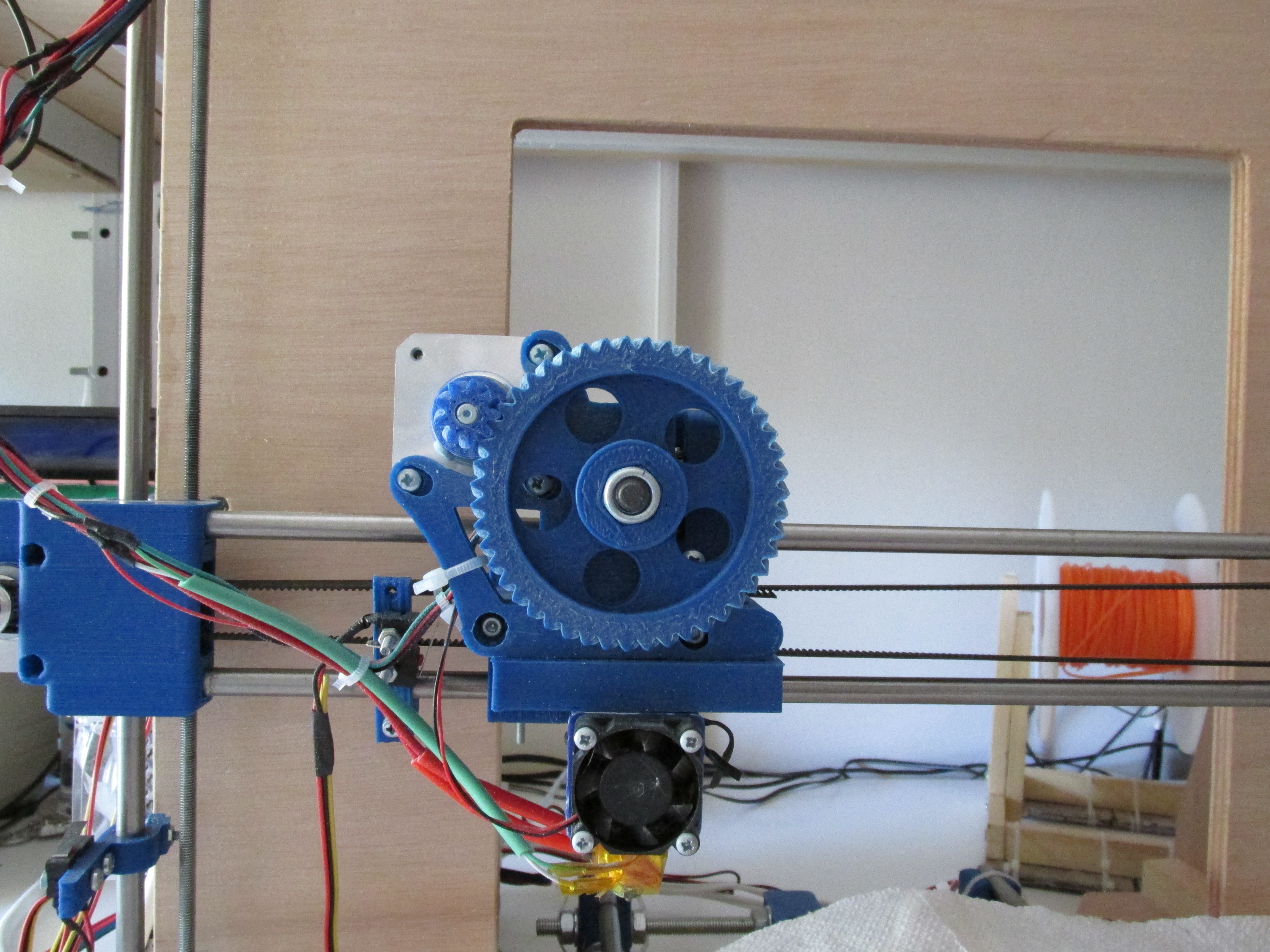
Below you can see the final result :
Below we can see again the hole result :
As we are going to see in the next section (electronics) we have to connect the extruder heater (resistor) at the D10 of Ramps,
the extruder motor at the E0 with the correct polarity and the
extruder thermistor at the T0 position.
The electronic diagram of the hole structure can be found below :
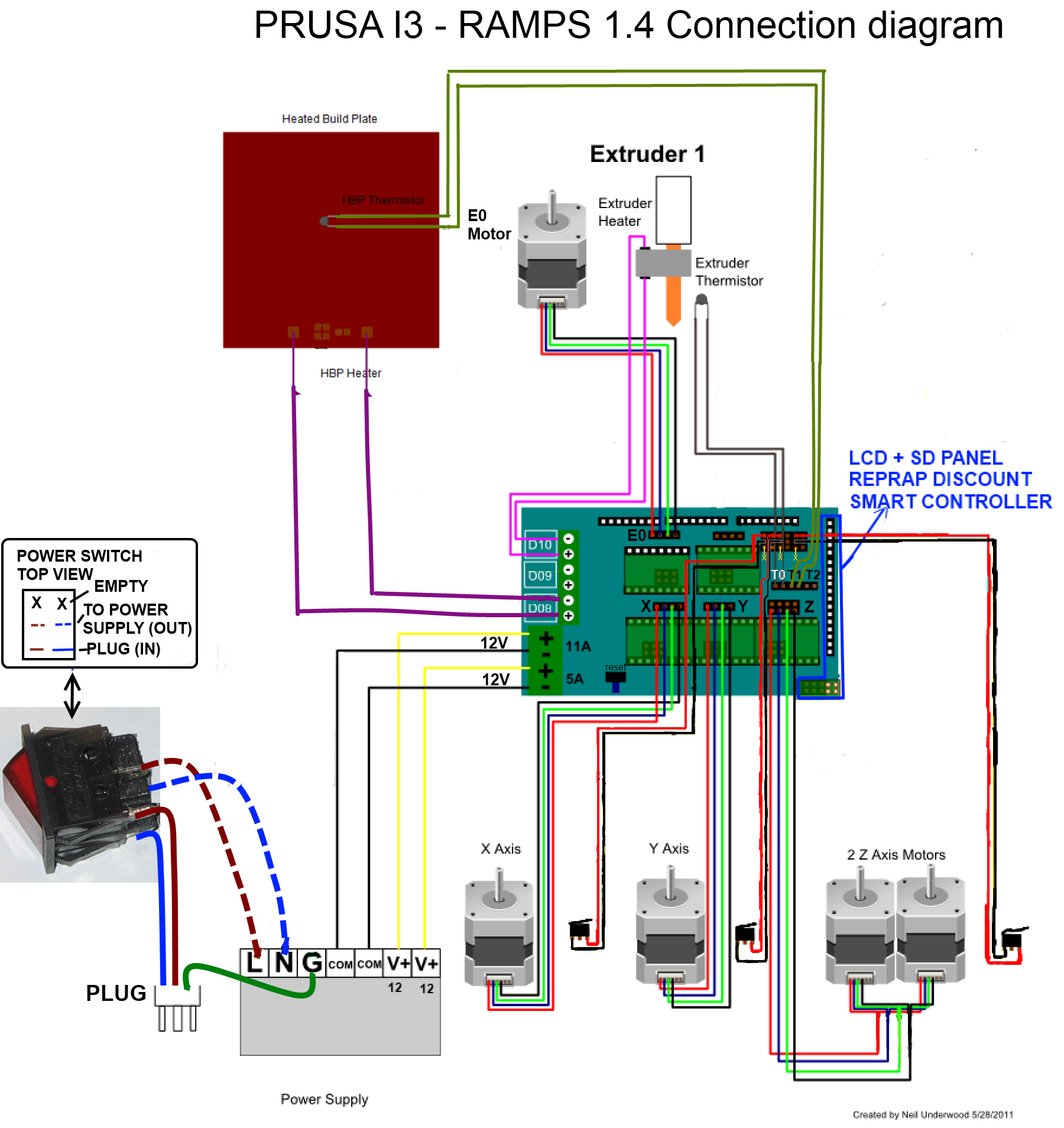
Also notice that the small extruder fan has to be directly plugged into our 12 V DC power supply. More detailed info you will find into the electronics section.
In the extras page 2 we will see how we can mount a single or a dual fan on our extruder in order to get better prints.
Final result :
In the next section we will discuss more about the electronics.
Section 1 - Wooden frame : part 1 - part 2 - part 3
Section 2 - Y Axis : part 1 - part 2 - part 3
Section 3 - X-Z axis : part 1 - part 2
Section 4 - Extruder : part 1 - part 2 - [[ part 3 ]]
Section 5 - Electronics : part 1 - part 2 - part 3
Section 6 - Coarse Calibration & Software : part 1 - part 2 - part 3
Section 7 - Fine Calibration & Software : part 1 - part 2 - part 3
Section 8 - Extras : part 1 - part 2 - part 3
Section 9 - Maintenance & Modding : part 1 - part 2