Constructing a 3D Printer [Prusa I3]
SECTION 6 - Coarse Calibration & Software - Page 1
Section 1 - Wooden frame : part 1 - part 2 - part 3Section 2 - Y Axis : part 1 - part 2 - part 3
Section 3 - X-Z axis : part 1 - part 2
Section 4 - Extruder : part 1 - part 2 - part 3
Section 5 - Electronics : part 1 - part 2 - part 3
Section 6 - Coarse Calibration & Software : [[ part 1 ]] - part 2 - part 3
Section 7 - Fine Calibration & Software : part 1 - part 2 - part 3
Section 8 - Extras : part 1 - part 2 - part 3
Section 9 - Maintenance & Modding : part 1 - part 2
Let's start with the coarse calibration of the machine.
It is now time to connect the y tray with the z axis.
Turn simultaneously by hand the two motors of the z axis in order to port the nozzle at least 3 cm above the y tray.
Now place the y axis table below the nozzle. Do not fix the y axis with the frame yet.
Start moving the tray back and forth by hand in order to make sure that the a distance (a) indicaded at the picture below is always the same.
Use a digital caliper in order to get more accurate readings.
Do the same with the other side of the tray (b)
If this not happens move the hole tray towards or backwards to you until the edge of the glass just covers the nozzle.
Make sure that the distances (a) and (b) are stable.
Once you are sure about the y axis you can screw it with the frame using 16 wood screws like the picture below.
Recheck the alignments of the tray (a,b,c) every time you screw a new woodcrew.
By the end of this procedure you have finished the coarse calibration.
Now you have to oil the linear, M5 and M8 bars using low viscosity motor oil (SAE 30).
Just dip a cotton swab into the motor oil and cover with oil the metallic moving parts.
Now we have to motorize our machine.
Make sure you have connected all the cables like the schematic below.

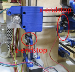
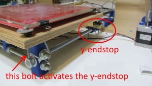
Also make sure you have placed the x,y,z endstops correctly by eye.
Always place the endstops in a ultra-conservative way.
The Z endstop place it always higher than is needed.
Arduino is needed to load the firmware of our 3d printer.
Download Arduino IDE version 1.8.X from the official site.
You can use the 1.8.4 version of Arduino located at Arduino software section.
Once you have downloaded and installed Arduino we need to install our firmware.
We are going to use Marlin firmware version 1.0.
We have a pre-configured version of Marlin for our direct I3 Prusa 3D printer that can be downloaded from here.
A newer preconfigured version of Marlin 1.1.4 can be downloaded from here.
If you want a more updated marlin version i recommend to download the latest stable version from the official marlin page.
I have also tested the Marlin 1.1.4 version and works perfectly well.
Unzip the "Marlin-Marlin_v1.zip" or "Marlin-1.1.4.zip" firmware and keep the zip files since you are going to minor changes into the unzipped files.
Run arduino press "File" > "Open" and load the "Marlin-Marlin_v1\Marlin\Marlin.ino" file.
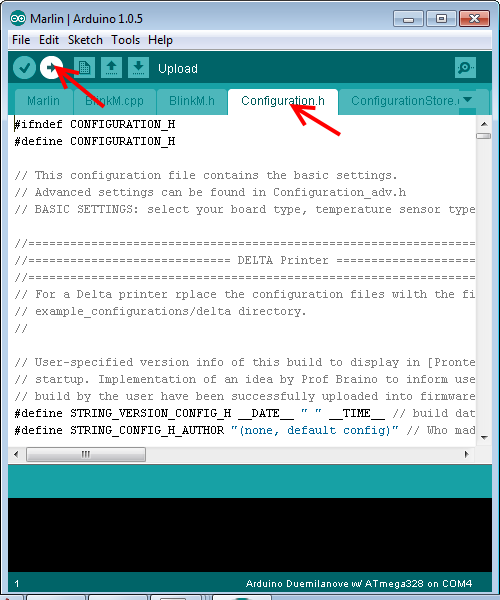
You have to focus on "Configuration.h" tab like the picture below :

From "Configuration.h" we can configure our 3D printer firmware.
Let's start from some theory. Let's find out how we can pre-calculate the x/y/z/e-steps.
The formula that give the X,Y steps/mm is :
steps/mm = ( (360/MOTOR_STEP_ANGLE) * (1/(MICROSTEPS)) ) / (BELT_PITCH * TOOTH_COUNT)
So in our case we have :
steps/mm = ( (360/1.8) * (1/(1/16)) ) / (2 * 20) = 80 step/mm for the X and Y axis.
For the Z axis the step formula is :
steps/mm = ( (360/MOTOR_STEP_ANGLE) * (1/(MICROSTEPS)) ) / (LEADSCREW_PITCH * GEAR_RATIO)
So in our case we have :
steps/mm = ( (360/1.8) * (1/(1/16)) ) / (0.8) *(1/1) = 4000 step/mm for the Z axis
For the extruder we have the formula below :
steps/mm = ( (360/MOTOR_STEP_ANGLE) * (1/(MICROSTEPS)) * (BIG_GEAR_TEETH / SMALL_GEAR_TEETH) ) / (HOB_EFFECTIVE_DIAMETER * PI)
So in our case (Greg's Wade Reloaded Extruder) we have :
steps/mm = ( (360/1.8) * (1/(1/16)) * (47 / 9) ) / (6 * 3.14) = 887 step/mm for the extruder.
The X/Y/Z steps should be spot on with the formulas. Very little variations should have with these three numbers.
On the other hand the Esteps is a rough estimation. It is better to start from 650 step/mm for the esteps So in your "Configuration.h" file a good starting point for the axis steps for this machine is :
#define DEFAULT_AXIS_STEPS_PER_UNIT {80.00,80.00,4000.00,650.00}
It is time to find out the optimal layer height values for Z axis.
This is a value that we will put in our slicer tool later.
For now just write down the valid layer heights of your machine.
The formula below helps you to select layer height in a way, that Z axis moves only by full step increments :
layer height = STEPS_INTEGER / (Z_AXIS_MICROSTEPS / (1/(MICROSTEPS)) )
For example if you set 65 integer steps your layer height would be :
layer height mm = 65 / (4000 / (1/(1/16))) = 0.260
for 64 steps would be :
layer height mm = 64 / (4000 / (1/(1/16))) = 0.256
for 63 steps would be :
layer height mm = 63 / (4000 / (1/(1/16))) = 0.252
for 62 steps would be :
layer height mm = 62 / (4000 / (1/(1/16))) = 0.248
for 61 steps would be :
layer height mm = 61 / (4000 / (1/(1/16))) = 0.244
for 60 steps would be :
layer height mm = 60 / (4000 / (1/(1/16))) = 0.240
As we can see a layer height of 0.26mm is obdainable like is the 0.24mm but a 0.25mm value is not a valid layer height for our machine.
So keep in mind that valid layer heights for our machine are :
0.06 / 0.08 / 0.1 / 0.12 / 0.14 / 0.16 / 0.18 / 0.2 / 0.22 / 0.24 / 0.26 / 0.28 / 0.30
Also keep in mind with our nozzle (0.4 diameter) we can not print layer heights more than 0.30 mm safely.
Best results are obtained when layer height is between 15-75% of nozzle diameter :
0.4*0.15=0.06 min layer height for a 0.4mm nozzle
0.4*0.75=0.30 max layer height for a 0.4mm nozzle
With the 0.4 E3D nozzle you can print easily down to 0.1mm.
Below that layer height it is better to use a smaller diameter nozzle and use ventilation.
For starters use 0.2 mm as layer height
An easy to use calculator for your prusa I3 can be found at calculator.josefprusa.cz
As you can see the default "Configuration.h" is already preconfigured for you.
At this file you should only do minor changes.
Let's see how we can upload our firmware and fine tune the configuration values.
First of all you need a normal printer usb cable 1,5m ( male USB Type A to male USB Type B )

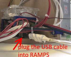
Plug your USB cable with the RAMPS board. I suggest to leave this cable permanently in the RAMPS port since it is relatively difficult to access it.
It is far better to unplug the 3D printer from the other end (PC).
Once plugged the printer into the PC in Windows 7 for the first time either a "Found New Hardware Wizard" Dialogue window will appear, or a dialogue baloon box "not successfully installed", either way just close the respective window.
Go to Start -> Control Panel -> System -> Device Manager.
You should see "unknown device" under "other devices" or "Arduino Mega" under "Ports".
If you see "unknown device" you should install the Arduino drivers.
To install the drivers right click over the "unknown device" and select "Properties".
Now select the "Update Driver ..." button
Select "Browse my computer for driver software".
Select "Browse".
Select "Ports (COM & LPT)".
Hit the "Have Disk..." button.
Select "Browse"
Go to arduino\drivers folder and load the "arduino.inf" file
Select "Ok"
Select "Arduino Mega 2560" then select "Next".
Select "Install this driver software anyway".
After a short while (it could be up to a few minutes depending on your computer speed) the success message should appear, then select "Close".
You should have now installed correctly the drivers under Windows.
If you have an Arduino Mega 2560 clone with the CH340G USB to serial chip you have to use the official drivers that can be downloaded from here, here or here
Now go to :
Start -> Control Panel -> System -> Device Manager -> Ports -> Arduino Mega
and find your COM port used by the USB cable.
In this example we see that the communication port is : COM8
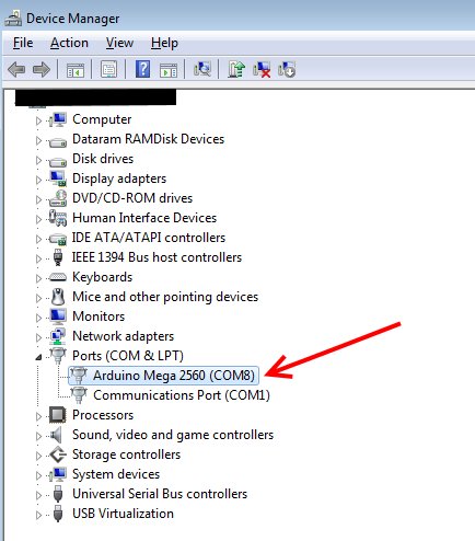
If Arduino Mega is not listed at Device manager even if you have installed the drivers take a look at the official documentation of arduino here
Run arduino press "File" > "Open" and load the "Marlin-Marlin_v1\Marlin\Marlin.ino" file.
A new arduino GUI window opens.
Close the old window
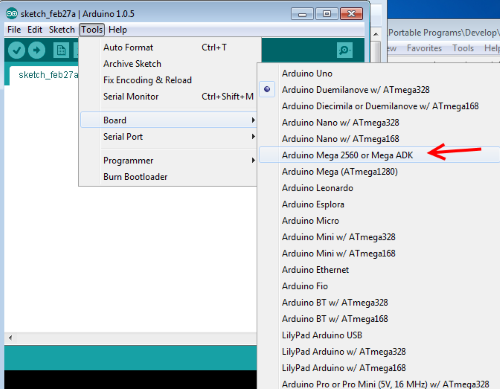
From "Tools" > "Board" select "Arduino Mega 2560"
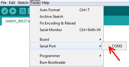
From "Tools" > "Serial Port" select the COM port found before (COM8 in our case)
Now hit the upload button like the photo below
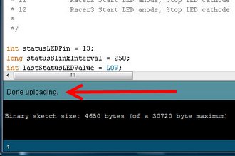
In a few seconds the firmware should be loaded at the arduino board.
You should get a "Done uploading" into the status bar like the picture below:
To summarize :
#define DEFAULT_AXIS_STEPS_PER_UNIT {80.00,80.00,4000.00,650.00} sets the number of stepper motor steps required to move the axis.
#define DEFAULT_MAX_FEEDRATE {500, 500, 1.2, 25} sets the maximum movement speed for each axis in mm/sec. Do not change these values.
#define DEFAULT_MAX_ACCELERATION {1000,1000,4,3000} controls the maximum acceleration of each axis.
Again the given settings are ok.
#define DEFAULT_ACCELERATION 3000 sets the acceleration for normal axis moves during a print. Do not change
#define DEFAULT_RETRACT_ACCELERATION 3000 sets the acceleration for extruder retracts. Do not change
Leave XYJERK , ZJERK EJERK as is.
Jerk is the rate of change of acceleration or in other words is the derivative of acceleration with respect to time
#define DEFAULT_XYJERK 10.0 // was 20.0(mm/sec) do not change
#define DEFAULT_ZJERK 0.4 // (mm/sec) do not change
#define DEFAULT_EJERK 5.0 // (mm/sec) do not change
Now it is time to tweak our USB to serial communication in order to avoid stalls after long prints.
Some important Windows settings that will improve the USB communication are :
1) Disable sleep mode
Go to :
Start -> Control panel -> Power options and set "Put trhe computer to sleep" : Never
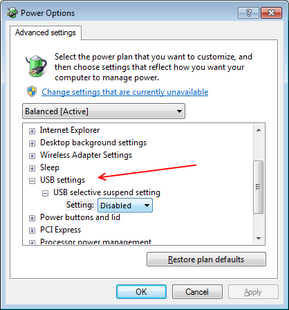
2) Disable USB selective suspend setting.
Go to :
Start -> Control panel -> Power options -> Change plan settings -> Change advanced power settings
Now click on "USB settings" -> "USB Suspend setting" -> "Disable"
3) Disable USB Root HUB power managment Go to : Start -> Control panel -> System -> Device manager.
The Device Manager window will open.
Expand the "Universal Serial Bus controllers" branch then double-click on the first "USB Root Hub" device, and choose the "Power Management" tab.
Uncheck the "Allow the computer to turn off this device to save power" and press the "OK" button.
Do the same for all "USB Root Hub" devices.
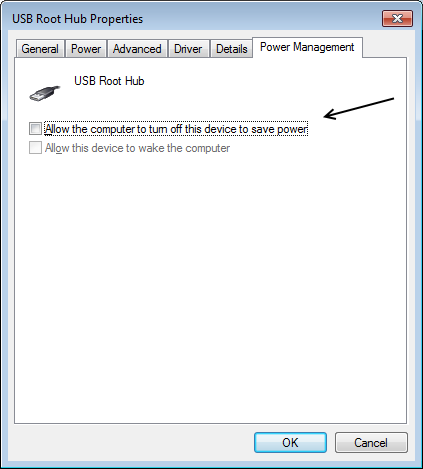
If you have "Generic USB Hub" voices under "Universal Serial Bus controllers" you have to do the same procedure for them too.
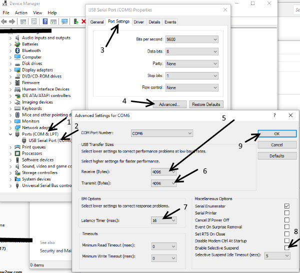
4) USB to Serial Driver settings These settings are not 100% important to do right now but it is usefull to know them in case you still have long prints stalled.
The original Arduino Mega 2560 uses the FTDI chip so go to :
Start -> Control panel -> System -> Device manager.
Click on "Ports (COM & LPT)" and double-click over "USB Serial Port"
On the "USB Serial Port properities" window click on the "Port Settings" tab and hit the "Advanced..." button.
If you have communication issues lower receive / transmit bytes , reduce "latency time" to 1 ms and make sure that "Enable Selective Suspend" is unchecked.
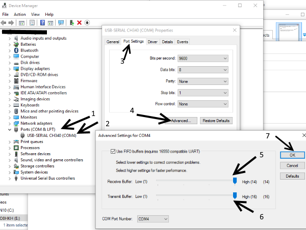
Similarly goes for the CH340 chip (Arduino Mega 2560 clone).
Try lowering the receive / transmit buffers.
If you still have communication issues try using a direct USB port for your 3D printer or use a powered USB Hub.
In the next page we will see how we can pilot and fine tune our 3D printer from our PC.
Section 1 - Wooden frame : part 1 - part 2 - part 3
Section 2 - Y Axis : part 1 - part 2 - part 3
Section 3 - X-Z axis : part 1 - part 2
Section 4 - Extruder : part 1 - part 2 - part 3
Section 5 - Electronics : part 1 - part 2 - part 3
Section 6 - Coarse Calibration & Software : [[ part 1 ]] - part 2 - part 3
Section 7 - Fine Calibration & Software : part 1 - part 2 - part 3
Section 8 - Extras : part 1 - part 2 - part 3
Section 9 - Maintenance & Modding : part 1 - part 2