


Constructing a 3D Printer [Prusa I3]
SECTION 8 - Extras - Page 3
Section 1 - Wooden frame : part 1 - part 2 - part 3Section 2 - Y Axis : part 1 - part 2 - part 3
Section 3 - X-Z axis : part 1 - part 2
Section 4 - Extruder : part 1 - part 2 - part 3
Section 5 - Electronics : part 1 - part 2 - part 3
Section 6 - Coarse Calibration & Software : part 1 - part 2 - part 3
Section 7 - Fine Calibration & Software : part 1 - part 2 - part 3
Section 8 - Extras : part 1 - part 2 - [[ part 3 ]]
Section 9 - Maintenance & Modding : part 1 - part 2
In order to make your 3D printer standalone you need to purchase an add on circuit that plugs into your ramps.
This tutorial is based on the RepRapDiscount Smart Controller.
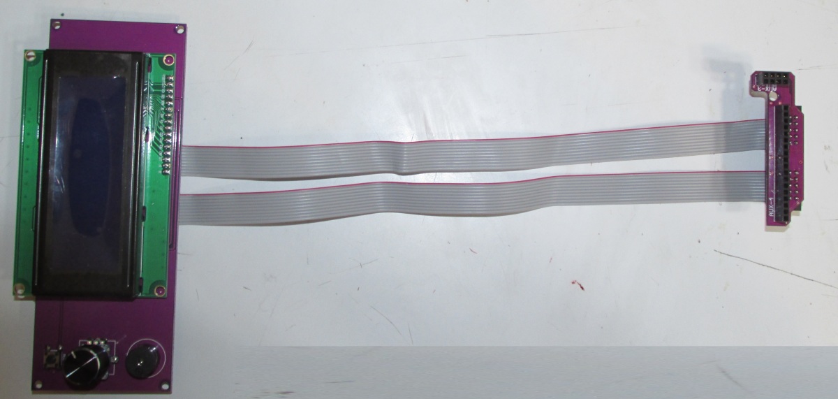
The Smart Controller circuit adds a 20 Character x 4 Line LCD display, a SD-Card reader, and rotary encoder into your printer.
After installing the Smart Controller you do not need a computer in order to pilot your 3D printer machine.
You can purchase Smart Controller from here
I have chosen the purple PCB one.
Before plugging the Smart Controller into the ramps you should follow these steps :
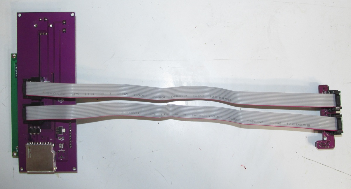
1) Plug the cables into the sockets. Notice the location of the two red coloured cables.
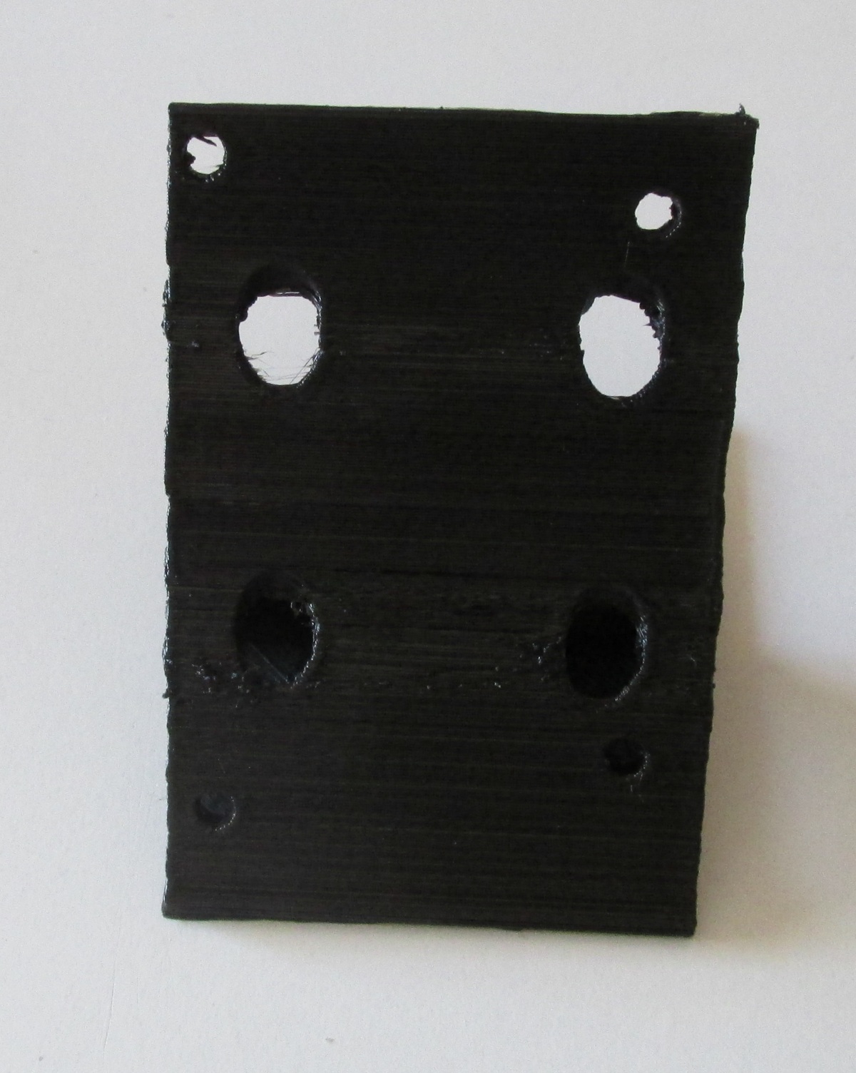
2) Now you should print the handle for the Smart Controller that can be downloaded from here or here
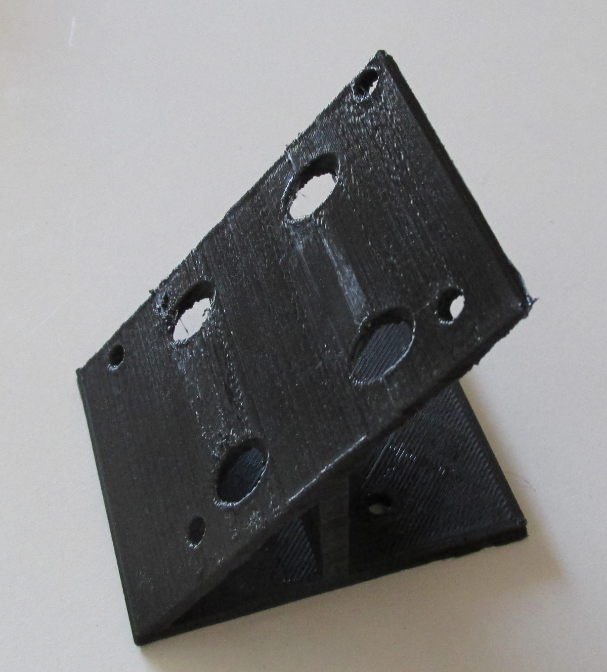
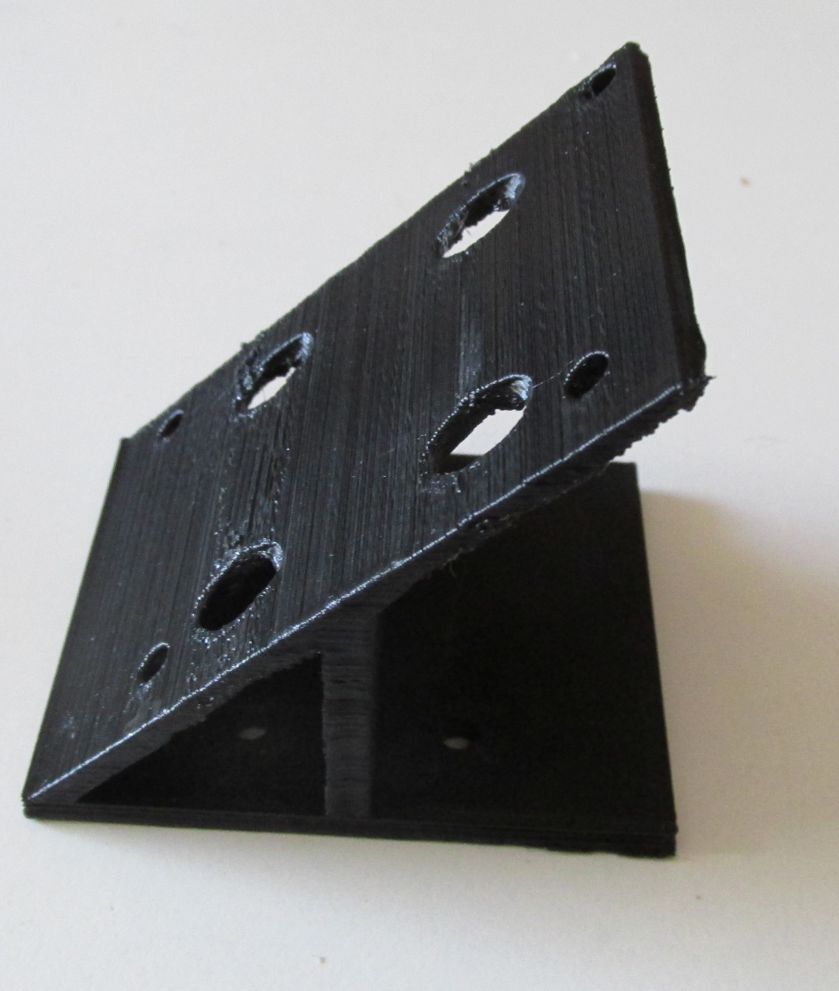
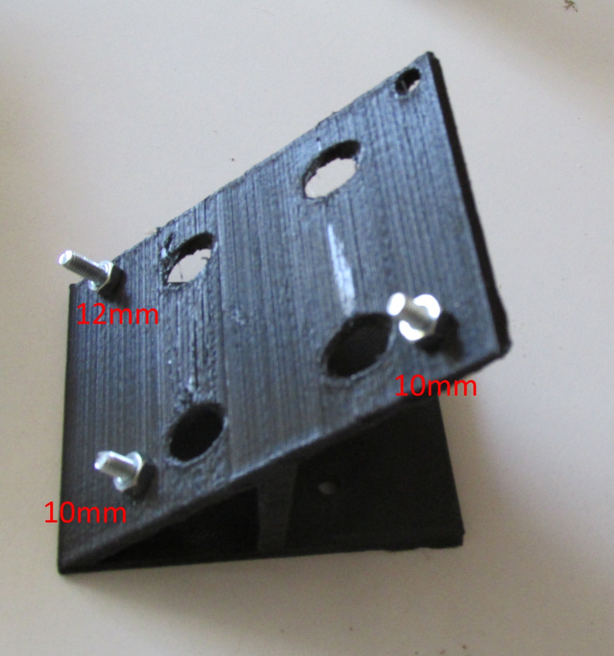
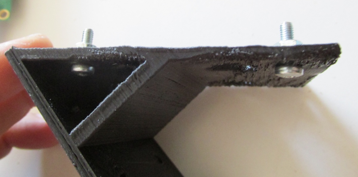
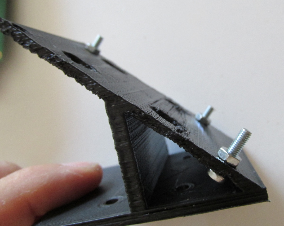
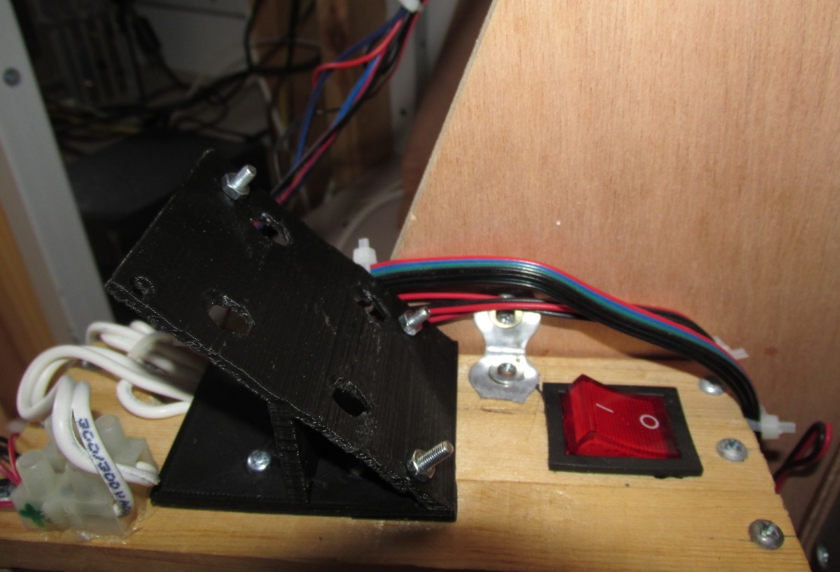
Now place the three M3 screws (two 10mm, one 12mm) and nuts like the photos below.
Tight well all three screws.
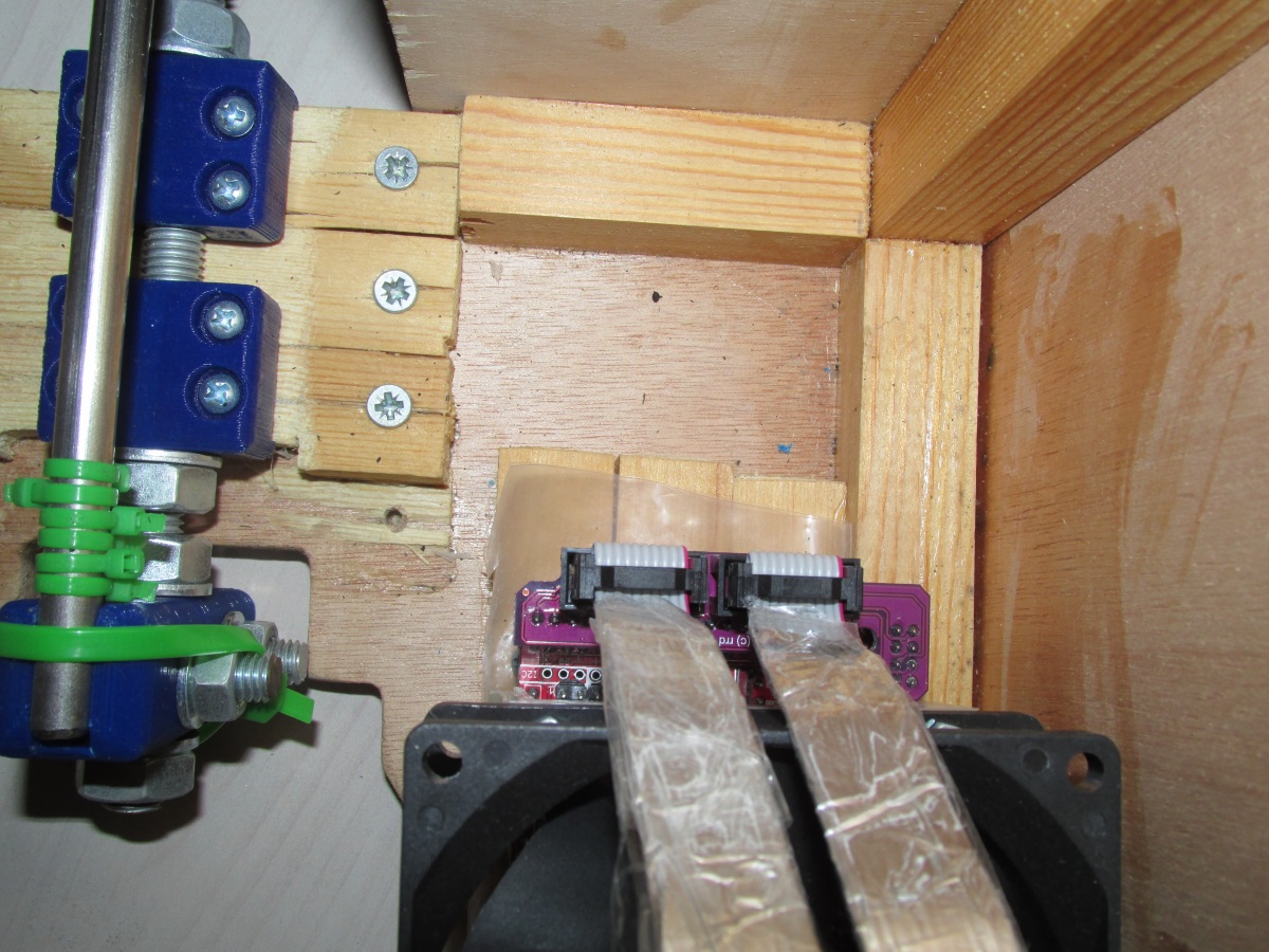
Now you have to isolate the cables of the Smart Controller.
This is not an optional step.
If you do not isolate the cables then you will have problems when you are going to transmit data from the SD card to ramps.
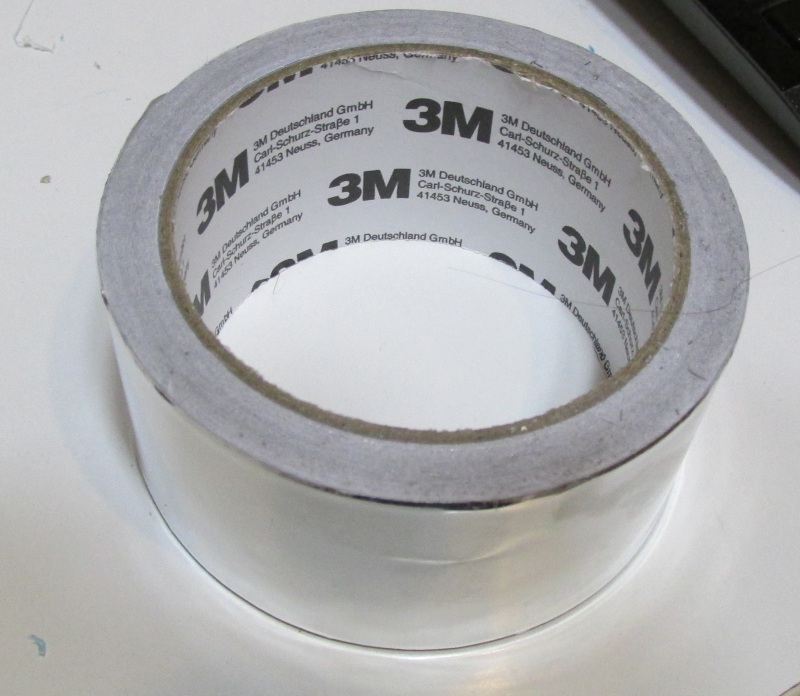
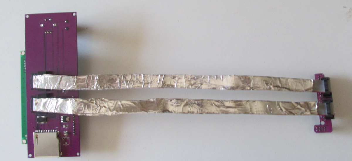
As first step using aluminium tape cover the cables.
If you do not have aluminium tape use aluminium foil.
Wrap the cables at least two times
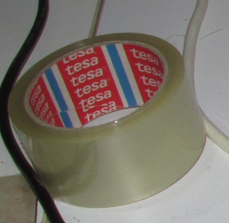
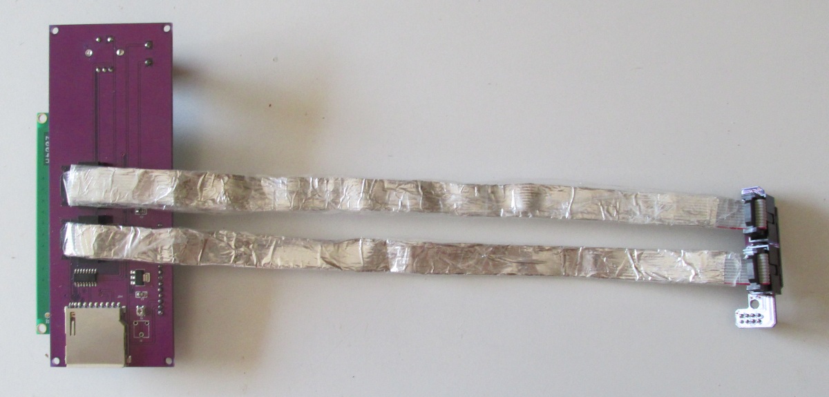
Now we have to add the external isolation of our newly shielded cable.
I have used clear tape but you could use and electrical tape.
By placing four small wood screws we mount the printed handle over the wooden power supply case like the picture below. Use the four 45 degree holes in order to pass the screwdriver.
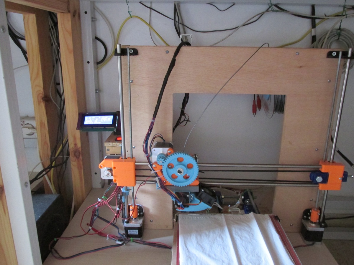
Now you can connect the jack of the Smart Controller to Ramps like the pictures below
Finally lock the Smart Controller using three more M3 nuts like the picture below.
Do not over-tight the nuts with the PCB.
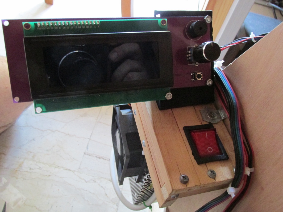
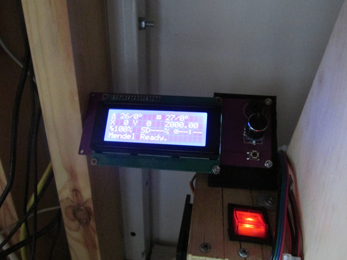
The final result should look something like this :
Now you should enable the Smart Controller from the marlin firmware.
Go to Arduino IDE and load "Marlin.ino"
Hit the "Configuration.h" tab and remove the "//" at the beginning of the line
#define REPRAP_DISCOUNT_SMART_CONTROLLER
In the newer marlin versions (1.1.4) you should also enable (by removing the "//" at the beginning of the line)
#define SDSUPPORT
At the same file also enable the SPEAKER by unommenting
#define SPEAKER
Save "Configuration.h"
Notice that in the new marlin firmware (1.1.4) if you get "Heating failed" when you trying to print from SD card you should change the
#define WATCH_TEMP_PERIOD 20
to
#define WATCH_TEMP_PERIOD 180
located at "Configuration_adv.h".
Do similarly for
#define THERMAL_PROTECTION_PERIOD 40
to
#define THERMAL_PROTECTION_PERIOD 180
Also you might want to disable
//#define SDCARD_RATHERRECENTFIRST
and
//#define SDCARD_SORT_ALPHA
in order to get alphabetical ordered filenames at the SD card use SD Sorter instead.
Always from "Configuration_adv.h" you can enable
#define ADVANCED_PAUSE_FEATURE
in order to enable filament changing. This setting is super useful if you want to change filament color in the middle of the print.
Simply during the printing from the LCD menu hit "Tune" > "Change filament" in order to change filament.
Press "Save" and then the "upload" button in order to update the firmware.
If you want to invert the direction of your LCD controller encoder you have to edit "pins_RAMPS.h" using Arduino GUI
Go to the :
#if ENABLED(REPRAP_DISCOUNT_SMART_CONTROLLER) section of the file
and swap the BTN_EN1, BTN_EN2 values like this :
#define BTN_EN1 33 //was 31
#define BTN_EN2 31 // was 33
Save and re-upload the firmware as always.
Now everything should work !
Buy and use a relatively small SD card formatted FAT not FAT32.
I have tested with success up to 8GB SD cards but i generally use smart controller with old 1-2GB SD cards. More details about SD cards and arduino can be found here
Notice that you can copy / delete files at your SD card with two methods.
The first method is fiscally unplug the SD card from your Smart Controller and load *.gcode files from your computer using a SD card reader.
This method is fast, secure and recommended.
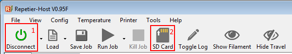
Another slow method is to use repetier in order to load or remove gcode files into the SD card without the need to unplug it from the Smart Controller.
First of all connect the computer with repetier and then hit the SD card button like the picture below.
Now at the new window you can add or remove files.
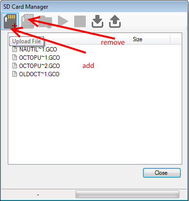
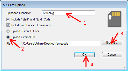
In order to add a file into the SD card fill the "Uploaded filename" with a really simple file name with at most six letters or characters and with the extension ".g" Do not use the extension ".gcode"
Example : test.g is correct
test-2.g is incorrect (remove the -)
test20.g is correct
Select "Upload external file"
Hit the "Browse" button and load your gcode file
Hit the "OK" button
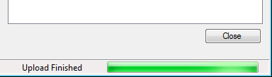
Wait till the bottom bar is full :
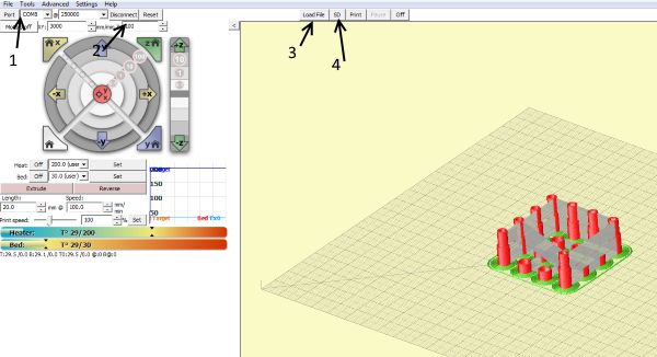
The same procedure can be done using pronterface.
Simply connect using pronterface and then hit the "load file" button. Once you have loaded your gcode press the "SD" button.
Then select the "SD Upload" option.
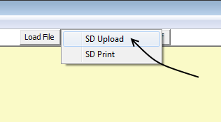
Rename the gcode file into a 8.3 format like "test.g" and upload the file.
In order to delete a gcode using pronterface just write "M30 test.g" and hit the "Send" button.
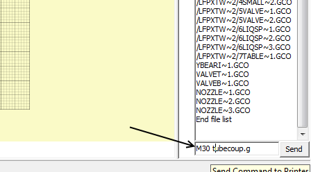
Notice: This transfer method is really slow.
Once transferred the files you can physically unplug the USB cable and shut down the computer.
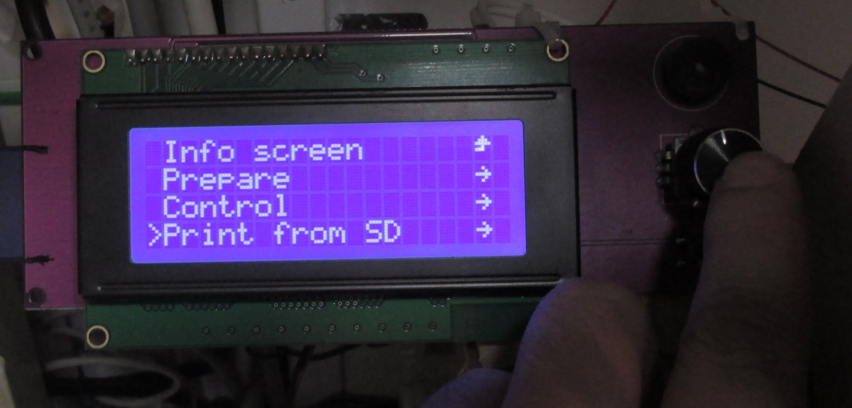
Plug the SD card with the gcode files at Smart Controller and power the printer.
Using the knob select "Print from SD"
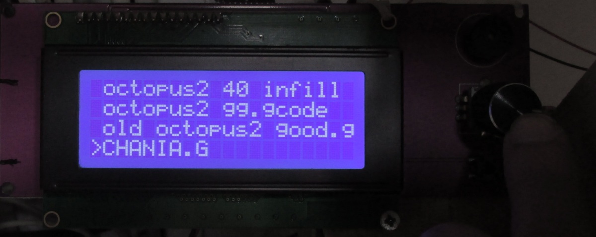
Now from the list select your file and you are ready to go.
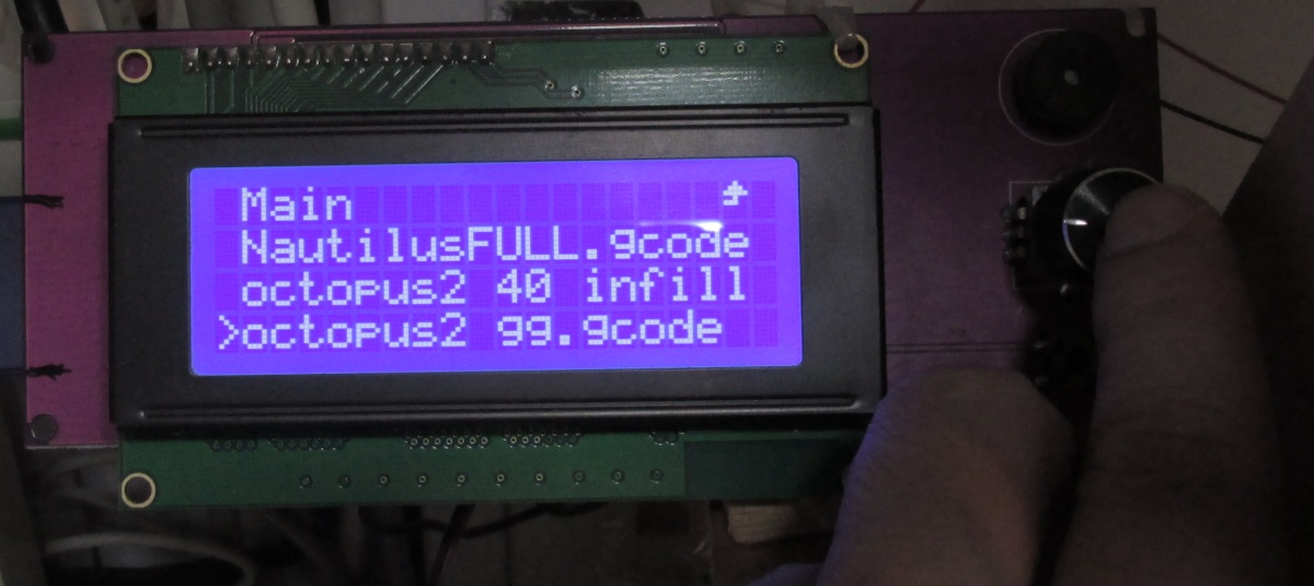
Notice that the transferred files from repetier have upper-case letters and .g extension
In the next and last section we will see how to maintain our 3D printer and how to do some modifications.
Section 1 - Wooden frame : part 1 - part 2 - part 3
Section 2 - Y Axis : part 1 - part 2 - part 3
Section 3 - X-Z axis : part 1 - part 2
Section 4 - Extruder : part 1 - part 2 - part 3
Section 5 - Electronics : part 1 - part 2 - part 3
Section 6 - Coarse Calibration & Software : part 1 - part 2 - part 3
Section 7 - Fine Calibration & Software : part 1 - part 2 - part 3
Section 8 - Extras : part 1 - part 2 - [[ part 3 ]]
Section 9 - Maintenance & Modding : part 1 - part 2